How do I attach wires to this little thing.
Jan 21, 2024 09:09:59 #
The APDS-9007 is an analog current output Ambient Light Photo Sensor, packaged in a miniature chipLED lead-free surface mount package. This device provides a Logarithmic response over a wide dynamic range of 3 lux to 70K lux and has a low sensitivity variation across various light sources.
What are you trying to make?
What are you trying to make?
Jan 21, 2024 09:35:01 #
DirtFarmer wrote:
Steady hand, small soldering tip, #30 wire, tinned, close-up lens.
The pads are a bit more than 0.1" wide. That's not all that bad.
They don't sell it in a packaged version with leads attached?
Keep a tube of burn salve nearby.
The pads are a bit more than 0.1" wide. That's not all that bad.
They don't sell it in a packaged version with leads attached?
Keep a tube of burn salve nearby.
👍👍👍
Jan 21, 2024 11:14:31 #
Brian S. wrote:
The APDS-9007 is an analog current output Ambient Light Photo Sensor, packaged in a miniature chipLED lead-free surface mount package. This device provides a Logarithmic response over a wide dynamic range of 3 lux to 70K lux and has a low sensitivity variation across various light sources.
What are you trying to make?
What are you trying to make?
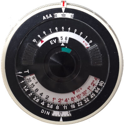
I want to make an exposure meter. The logarithmic response is excellent for an exposure meter.
Jan 21, 2024 11:18:24 #
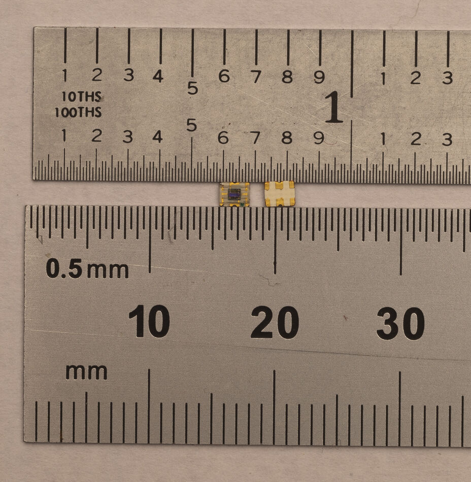
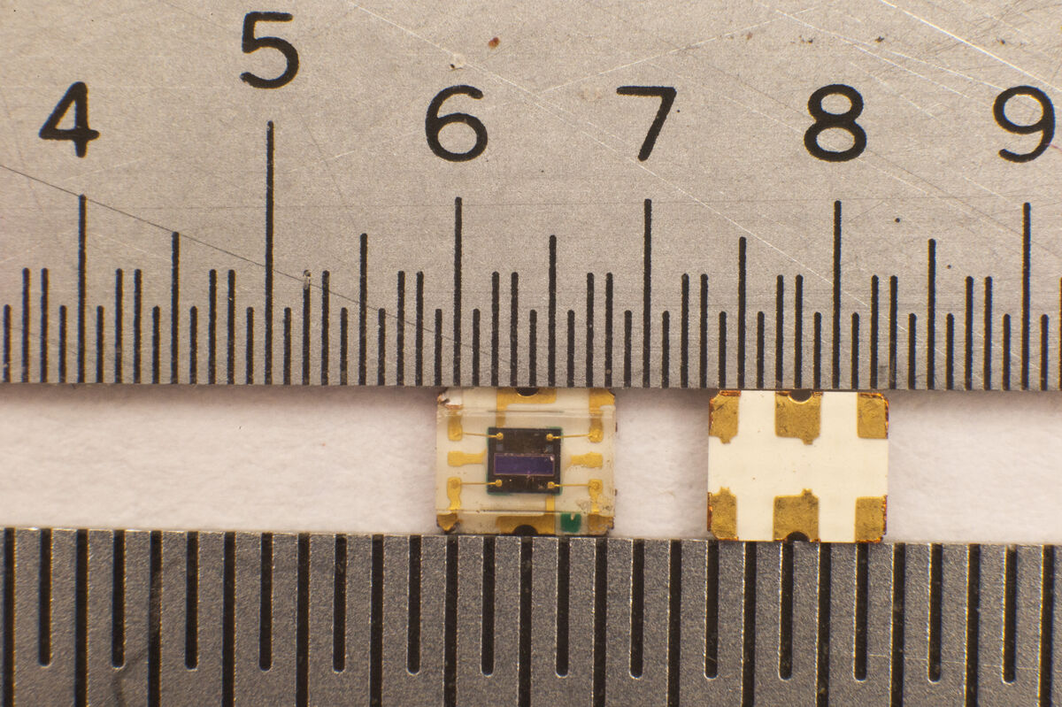
Well a couple more pictures so you can see how small it is. The one on the left is the front side and I can't solder it that side because the tab is under the plastic. I can solder the wires to the back side but a light tug on the wire would break off the tab.
I include 2 scales. The top scales is marked in 100th of an inch. The bottom is 0.5mm.
I include 2 scales. The top scales is marked in 100th of an inch. The bottom is 0.5mm.
Jan 21, 2024 11:34:42 #

BebuLamar wrote:
Well a couple more pictures so you can see how small it is. The one on the left is the front side and I can't solder it that side because the tab is under the plastic. I can solder the wires to the back side but a light tug on the wire would break off the tab.
I include 2 scales. The top scales is marked in 100th of an inch. The bottom is 0.5mm.
I include 2 scales. The top scales is marked in 100th of an inch. The bottom is 0.5mm.
You are not equipped to construct a circuitboard, but could you fashion a socket in a plastic tab that would give a larger area to attach your wires? Then have contacts from the wire connection points in that tab that will complete the routing of the circuitry to the pads on the chip?
Jan 21, 2024 11:37:38 #

BebuLamar wrote:
I have this light sensor which is the Avago APDS-9007. I need to attach 4 wires to the 4 corners of the chip. It's intended to mount to a circuit board but I can' make a circuit board. Any idea?
The numbers are 1/10th inches.
The numbers are 1/10th inches.
I would worry about the circuit board first. Once you figure that out, you can find a needle point soldering pen. some of these pens are battery operated.
Jan 21, 2024 11:50:31 #

BebuLamar wrote:
I have this light sensor which is the Avago APDS-9007. I need to attach 4 wires to the 4 corners of the chip. It's intended to mount to a circuit board but I can' make a circuit board. Any idea?
The numbers are 1/10th inches.
The numbers are 1/10th inches.
This is a SMD chip intended to be soldered by WAVE method on a PCB board which was primed with solder paste.
Design or copy a PCB layout (I use KiCAD for that) with the right footprint and include regular trough hole pads.
Use heat gun for soldering... about 200°C for 5 seconds should be OK.
Or better yet, hire a pro.
Jan 21, 2024 12:10:32 #

Longshadow wrote:
Very small wires and very small soldering iron.
Right or better yet a wire bonder, if he has access to a free one/loaner.
Jan 21, 2024 13:32:43 #
aphelps
Loc: Central Ohio
DirtFarmer wrote:
l have never had a problem soldering to gold plated wires.
Gold solders very well. As with any soldering, shine and clean before attempting to solder. A very fine iron and tip. Might even file a fine tip.
A lighted magnifier will be necessary.
After 65 years of soldering experience I would not attempt it today.
Jan 21, 2024 13:54:54 #
Barre
Loc: Fairfax Co, VA
BebuLamar wrote:
I have this light sensor which is the Avago APDS-9007. I need to attach 4 wires to the 4 corners of the chip. It's intended to mount to a circuit board but I can' make a circuit board. Any idea?
The numbers are 1/10th inches.
The numbers are 1/10th inches.
Know any jewelers?
Jan 21, 2024 16:33:34 #
Jan 21, 2024 20:43:16 #
Lost Again
Loc: Middle of nowhere Oregon
When you figure out how to hold each wire in place try to use a needle with superglue or a thinned epoxy mix.
Bad idea/ Let me know why.
Bad idea/ Let me know why.
Jan 21, 2024 21:03:35 #
therwol
Loc: USA
Lost Again wrote:
When you figure out how to hold each wire in place try to use a needle with superglue or a thinned epoxy mix.
Bad idea/ Let me know why.
Bad idea/ Let me know why.
Superglue and epoxy are non-metallic and don't conduct electricity like solder. Even if you think you have a good contact between wire and foil, the glue will creep under the wire and act as an insulator.
Jan 22, 2024 07:30:16 #
BebuLamar wrote:
I have this light sensor which is the Avago APDS-9007. I need to attach 4 wires to the 4 corners of the chip. It's intended to mount to a circuit board but I can' make a circuit board. Any idea?
The numbers are 1/10th inches.
The numbers are 1/10th inches.
This appears to be an SMT (surface mount) sensor chip that is soldered onto a ceramic substrate which is then often mounted to a larger circuit board or mounted into some type of socket. We often mounted and removed items similar to this where I worked.
First, those are gold-plated leads and accept regular solder readily. In fact, many circuit boards today are plated with very thin layers of gold to improve solderability and prevent oxidation.
Since this is an SMT chip, it is probably best to attach to the pads on the opposite side of the ceramic substrate, which is not shown in your photo but is shown in the later diagram. This will give you better attach points and help protect the sensor itself from heat if you try to attach closer to the chip on the top.
Note your second diagram. I think you will need to attach more than 4 wires. The sensor chip appears to have attachments on the bottom of the sensor chip itself which are shown as leads coming out from under the sensor itself and going to the edge and to attachments on the bottom of the ceramic holder. One of these other attachments points appears to be a ground which is usually important for most applications.
Use a lower-wattage solder iron and if you have it 63/37 solder which is the ideal solder for miniature circuits due to its melting point. Wires should be small such as stranded 18-24 ga. Heavier wires will require more heat which you do not want. I would go with the smaller 24 ga wire since it will require less heat to solder. This appears to be a very low current device so large wires will not be needed. Tin the wires first and leave a small bit of solder. That will make attaching the wires quicker and less stressful on the chip. With a good soldering iron and proper technique, you should be able to attach a wire in less than a 3-5 seconds. If you find yourself taking longer, stop and let it piece cool off.
Jan 22, 2024 07:55:23 #
Red6 wrote:
This appears to be an SMT (surface mount) sensor c... (show quote)
I am looking for a circuit board. I can solder the 24 ga wire to the chip OK but a slight pull on the wire will break the tab off. There are 6 tabs but only 4 are used.
If you want to reply, then register here. Registration is free and your account is created instantly, so you can post right away.