Old Photogenic Flashmaster & 3 heads
Mar 15, 2019 07:43:54 #
One unique feature of the FlashMaster line is that the power ratio
of the light outputs is controlled by a removable plug. Each plug
sets a particular ration for all four lights.
In the AA01 and AA01A supplies, the plugs are round (they fit an
11-pin tube socket). The first plug, #1, is designed to be inserted
in either of two positions. In one position it gives 100 Watt-seconds
on each plug; in the other it gives 50 Watt-seconds on each plug.
I only own three plugs, #1, #2 and #3, but I've been able to find out
about a bunch more from various sources. (Please note that the light
jacks (lights) on the front of the supply are numbered from right to
left, not left-to-right as one would expect.)
# POSITION LIGHT: 1 2 3 4
-- ------------ --- --- --- ---
1 100WS x 4 100 100 100 100
1 50WS x 4 50 50 50 50
2 400WS COM 1,2,3,4 |---------- 400 -----------|
3 200WS 1,100WS 2, 100WS 3,4 200 100 |-- 100 ---| Y
4 200WS 1, 100WS 2, 50WS x 2 200 100 50 50 N
5 200WS COM 1,2; 50WS x 2 |-- 200 --| 50 50 N
14 100WS 1, 50WS x 3 100 50 50 50 N
21 350WS COM 1,2,3; 50WS 4 |------ 350 ------| 50 N
24 200WS 1; 50WS x 3 200 50 50 50 N
29 300WS COM 1,2,3,4 |----------- 300 ----------| N
61 200WS COM 1,2; 150WS 3; 50 |-- 200 --| 150 50 N
62 300WS COm 1,2; 50WS x 2 |-- 300 --| 50 50 N
63 250WS COM 1,2; 100WS, 50WS |-- 250 --| 100 50 N
64 150WS 1, 100WS 2; 50WS x 2 150 100 50 50 N
65 250WS COM 1,2; 150WS COM |-- 250 --| |-- 150 --| N
66 300WS COM 1,2,3; 100WS 4 |------- 300 ------| 100 N
69 150WS COM 1,2; 250WS cOM |-- 150 --| |-- 250 --| N
PLUG WIRING
# CONNECTED PINS
Position A Position B
-- ------------------- --------------------------------------
1 1-2, 3-4, 5-6, 7-10 7-8(n.c.), 9(n.c.)-10, 11(n.c.)-1, 2-5
2 1-2-3-4-5-6-7-10
3 1-3, 2-4-7-10, 5-6
Photogenic went to a square plug for later models in the FlashMaster line.
I was never able to get a schematic for the AA01 (Photogenic did not return
my two e-mails), but was able to figure out how the plug wiring works,
using the information in the Instruction Manual and Parts List for
a slightly newer model (which I believe to be the AA01A) on Butkus.org:
https://www.butkus.org/chinon/flashes_meters/photogenic_machine_company/electronic_flashmaster/electronic_flashmaster.htm
The section "Information for the Electronics Serviceman" was particularly
helpful. (Unfortunately, the scan is missing the schematic diagram, as
well as the list of plugs.)
The power supply has four jacks for lights, referred to in the manual as
J1, J2, J3 and J3 (and numbered on the front panel 1 to 4, from righ to left).
Each jack is connected to a capacitor, which when charged holds 50 Watt-seconds
of power. Jack and capacitor are connected to a pin the "power plug" socket.
In addition, there are four more capacitors, also 50 Watt-seconds when charged,
each of which is connected to a pin in the "power plug" socket. By using a
"power plug" that jumps the appropriate pins, these four capacitor can be connected
in parallel with the any jack in any combination.
There is one additional wrinkle: not only can jumpers in the "power plug"
connect caps to jacks, they can connect jacks to jacks. That means that
two or more jacks can share the same capacitors, and hence that the power
will be split between the lights connected to those "common" jacks.
The pinouts for the round "power plug' socket are:
PIN JACK POWER
1 J4 50WS
2 50WS
3 J3 50WS
4 50WS
5 50WS
6 J2 50WS
7 J1 50WS
8 n.c.
9 n.c.
10 50WS
11 n.c
The best way to think about this is as three sets of pins:
Jack + Cap, Cap only, and no connection.
This can be represented as a "connect the dots" diagram:
PIN JUMPERS PIN
1 J4--50Ws * * 2 50Ws
3 J3--50Ws * * 4 50Ws
6 J2--50Ws * * 5 50Ws
i
7 J1--50Ws * * 10 50Ws
No connection: * * *
Pin: 8 9 11
Here are the wiring of the plugs I have:
PLUG #1
# POSITION LIGHT: 1 2 3 4
-- ------------ --- --- --- ---
1 A: 100WS x 4 100 100 100 100
1 B: 50WS x 4 50 50 50 50
Wiring:
Position A: 1-2, 3-4, 5-6, 7-10
PIN JUMPERS PIN
1 J4--50Ws *--------------------* 2 50Ws
3 J3--50Ws *--------------------* 4 50Ws
6 J2--50Ws *--------------------* 5 50Ws
i
7 J1--50Ws *--------------------* 10 50Ws
No connection: * * *
Pin: 8 9 11
Effective wiring when rotated:
Position B: 7-8(n.c.), 9(n.c.)-10, 11(n.c.)-1, 2-5
PIN JUMPERS PIN
1 J4--50Ws *--------------. .--* 2 50Ws
| }
3 J3--50Ws * | | * 4 50Ws
| |
6 J2--50Ws * | `--* 5 50Ws
|
7 J1--50Ws *------. .---}-----* 10 50Ws
No connection: * * *
Pin: 8 9 11
PLUG #2
# POSITION LIGHT: 1 2 3 4
-- ------------ --- --- --- ---
2 400WS COM 1,2,3,4 |---------- 400 -----------|
Wiring: 1-2-3-4-5-6-7-10
PIN JUMPERS PIN
1 J4--50Ws * * 2 50Ws
| |
3 J3--50Ws * * 4 50Ws
| |
6 J2--50Ws * * 5 50Ws
| |
7 J1--50Ws *--------------------* 10 50Ws
No connection: * * *
Pin: 8 9 11
# POSITION LIGHT: 1 2 3 4
-- ------------ --- --- --- ---
3 200WS 1,100WS 2, 100WS 3,4 200 100 |-- 100 ---|
Wiring: 1-3, 2-4-7-10, 5-6
PIN JUMPERS PIN
1 J4--50Ws *--. * 2 50Ws
| |
3 J3--50Ws *--' .-----* 4 50Ws
|
6 J2--50Ws * | * 5 50Ws
i |
7 J1--50Ws *----------------+-----* 10 50Ws
No connection: * * *
Pin: 8 9 11
Mar 15, 2019 08:33:49 #
E.L.. Shapiro wrote:
At one time I had the schematics for all the Photo... (show quote)
Thanks again for your help, E.L. Shapiro.
I sent two e-mails to sales@photogenic.com (the only address on the
coporate website), a week apart, asking about the schematic, but never
heard back from them. I guess it's become the kind of company that only
responds to orders.
Fortunately, with the good information you provided, and the
manual I found at Butkus.org, I was able to figure out everything
I needed to know to get the unit working.
I also wrote a cmoputer program with a database of power plugs,
and an algorithm to figure out the power ratio of any plug wiring.
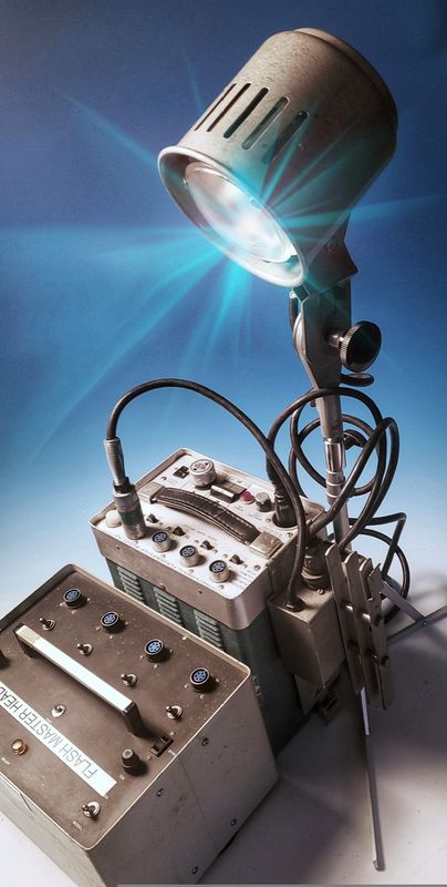
So far I am very happy with the lights. As you said the umbrella
light is wonderful (I also have a white diffuser for the reflective
umbrella), and has a nice bright modeling light. IT's a very sturdy
light, with the AA33H light stand, even outside it didn't blow down.
The AA12SC adjustble modeling/flood light with 16" parabolic reflector
is something I really want to experiment with. In the modeling setting,
it's sort of like a silver beauty dish, but much narrower angle
(45 degrees). The manual says its intended to be used 36" to 42" from
the sitter, and that it gives a lot of control over feathering. That I
can believe, because the light has a definite edge and it's a very
stable light.
Both the AA12SC 16" light and even the two AA11 wide-angle lights are less
contrasty than I expected, given the small size of the reflectors. I suppose
it's because the Photogenic H4-1 flashtube assembly includes a fairly
large ground glass dome diffuser.
I haven't tried the AA41 barn door yet. It fits the AA11s.
All the lights are really well made. There are a few dents and dings,
and I had to repair one power cord, but overall I'm very impressed.
Right now I'm using the standard 1072 modelings lights in the AA12SC
16" light and the two AA11 wide-angle lights, but I might try the
brighter ones that you suggested.
About my only complaint is that the flashtubes have to be removed for
transport, since they plug straight in and are only held in place by
friction. But after all, these are studio flash heads.
Mar 15, 2019 10:03:04 #

The equipmet you have acquired is apparently in excellent condition and what with the additional tune ups and maintenance you applied, it will provide many years of reliable service.
You probably know not to plug in or disconnect any of the lamp heads or the power-plugs when the unit is charged up and ready to fire. It is best to turn off the power and wait until the ready light extinguishes before making any of theses disconnections and reconnections. If this is not observed, there is sufficient arcing to damage the male and female connectors. I also find that a little WD-40 on a Q-tip occasionally applied to the surface of the female connectors prevents corrosion, moisture and anythg that can interfere with good contact and cause arcing.
Aesthetically speaking, as per lightg technique, the pan and parabolic reflectors you have are classics for portrait feathering techniques. The frosted glass outer envelopes provide a diffused "hot spot" at the center of the beam. Feathering the light so that the edge of the beam strikes the subjects will provide even light across the mask of the face and excellent rendition of texture and good specular highlights. The 16" parabolic reflector and lamphead has the same aesthetic qualities of the Photogenic Studiomaster units. As you indicated, it has a variable beam control. I found that if the aforementioned feathering method, the best position is where the porcelain plate that houses the flash tube socket is flush with the inner opening of the reflector.
Photogenic makes barn doors and diffusion panels made specifically for the 16 inch parabolic reflector. They may be available on the used market or still be in production in that the 16" parabolic is compatible with current Photogenic Powerlight mono-lights. Over the years, they have never changed their reflector mounting system so your older system is fully compatible with all their current reflectors including a beauty-light, and soft-box couplings.
A good setup is using the umbrella light (with a white umbrella) as a fixed fill source and using the 16" parabolic as a main. The other lights can serve as kickers and background lights. There are smaller lamp heads that can be fitted with snoots and barn-doors which would make for good hair and background lights. Another alternative is to use the umbrella head with that silver reflector, that you have, as a main source with a flat reflecto as a fill. 2 of those pans on a white background make for a great high key system.
I appreciate your safety warning. I always include this information whenever I write about repairs and maintenance of electronic flash gear. I always warn folks that are not familiar with high voltage servicing that even smaller speedlights can harbor lethal or damaging voltages that can cause shock, burns, nerve damage and/or death. It's not the kinda stuff that uninitiated folks shoud poke around into with a screwdriver. I also warn against discharging the capacitors by shorting them out with a screwdriver. I still have several 500 ohm 25 watt wire wound resistors connected to insulated probes and alligator clips, just incase I need to repair a unit or change a capacitor. Most people don't know about the residual charge that can remain even after proper discharging.
Mar 16, 2019 00:13:40 #
E.L.. Shapiro wrote:
The equipmet you have acquired is apparently in ex... (show quote)
Thanks again for the technical information that made this fun project possible,
and your priceless tips on using this system.
Forgot to mention that the 11" barn doors has a removable diffuser.
I've got quite a few options now for now for light, between the FlashMaster,
my old Buff "White Lightening" monolight, and various smart flashes,
dumb flashes, photoflood banks and quartz-halogen cinelights--and assorted
light modifiers.
It looks like a junkyard--but it keeps on working. And I've always found
there's a lot of truth in that proverb about "The devil you know..." And
it's true: "They don't build stuff like they used to."
Mar 16, 2019 00:17:45 #
Looks like I didn't format this table correctly, so here it is again:
Partial List of Power Plugs for the Photogenic FlashMaster AA01
(round 11-pin socket)
# POSITION LIGHT: 1 2 3 4
-- ------------ --- --- --- ---
1 100WS x 4 100 100 100 100
1 50WS x 4 50 50 50 50
2 400WS COM 1,2,3,4 |---------- 400 -----------|
3 200WS 1,100WS 2, 100WS 3,4 200 100 |-- 100 ---|
4 200WS 1, 100WS 2, 50WS x 2 200 100 50 50
5 200WS COM 1,2; 50WS x 2 |-- 200 --| 50 50
14 100WS 1, 50WS x 3 100 50 50 50
21 350WS COM 1,2,3; 50WS 4 |------ 350 ------| 50
24 200WS 1; 50WS x 3 200 50 50 50
29 300WS COM 1,2,3,4 |----------- 300 ----------|
61 200WS COM 1,2; 150WS 3; 50 |-- 200 --| 150 50
62 300WS COm 1,2; 50WS x 2 |-- 300 --| 50 50
63 250WS COM 1,2; 100WS, 50WS |-- 250 --| 100 50
64 150WS 1, 100WS 2; 50WS x 2 150 100 50 50
65 250WS COM 1,2; 150WS COM |-- 250 --| |-- 150 --|
66 300WS COM 1,2,3; 100WS 4 |------- 300 ------| 100
69 150WS COM 1,2; 250WS cOM |-- 150 --| |-- 250 --|
Feb 6, 2020 20:40:30 #
jgriessen4
Loc: Austin Texas
Bipod wrote:
I'm still going to try to get ahold of the Flashmaster schematic if I can, for future reference.
I'm still going to try to get ahold of the Flashmaster schematic if I can, for future reference.
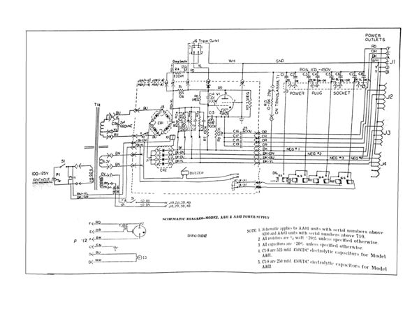
Here's a schematic I scraped off an ebay sale of a paper manual:
https://www.cibolo.com/docs/flashmaster-aa01-schem.png
Feb 6, 2020 20:46:49 #
jgriessen4
Loc: Austin Texas
Here is that small image file as attachment, since this is a good place for it to be for a long while.
Feb 6, 2020 21:11:11 #
jgriessen4 wrote:
Here's a schematic I scraped off an ebay sale of a paper manual:
https://www.cibolo.com/docs/flashmaster-aa01-schem.png
https://www.cibolo.com/docs/flashmaster-aa01-schem.png
Very helpful--and great to have the image posted here. Thanks a million!
Feb 6, 2020 22:29:20 #
Hello,
I have a Flashmaster AA17 umbrella head and need to change the modeling lamp. Can you tell me how to get at the bulb under the glass lens? Does the whole lens, and flash tube pull out to get at the bulb?
Thanks,
I have a Flashmaster AA17 umbrella head and need to change the modeling lamp. Can you tell me how to get at the bulb under the glass lens? Does the whole lens, and flash tube pull out to get at the bulb?
Thanks,
Feb 6, 2020 23:03:37 #
gwagner wrote:
Hello,
I have a Flashmaster AA17 umbrella head and need to change the modeling lamp. Can you tell me how to get at the bulb under the glass lens? Does the whole lens, and flash tube pull out to get at the bulb?
Thanks,
I have a Flashmaster AA17 umbrella head and need to change the modeling lamp. Can you tell me how to get at the bulb under the glass lens? Does the whole lens, and flash tube pull out to get at the bulb?
Thanks,
I have that lamp head. There are 3 clips that retain the lens. Loosen the screws, remove the glass and replace the modeling lamp. The flash tube encircles the modeling lamp and does not need to be removed. Disconnect the head from the power pack before servicing it. The umbrella head takes a screw base 250 watt quartz lamp. Handle the new lamp with a cloth or glove when installing it. Finger marks and smudges left on the lamp will shorten its life. Reinstall the lens after installing the lamp.
Feb 6, 2020 23:11:05 #
jgriessen4
Loc: Austin Texas
What's the plain aluminum box in lower left of the photo? Looks like generic switches, mil connectors with thread on them -- home brew capacitor banks triggered by wire?
Feb 6, 2020 23:28:06 #
jgriessen4 wrote:
What's the plain aluminum box in lower left of the photo? Looks like generic switches, mil connectors with thread on them -- home brew capacitor banks triggered by wire?
For many years I ran a side business dealing in electronic flash repairs, modifications, and custom builds. That box is a custom made power pack that is comparable with FLASHMASTER heads. 400
W.S and 4 sockets. I made it in 1975 and it is still in service. We equipped studios and professional sports venues.
I have 2- 2400 W.S packs that are comparable with Speedotron heads. I use them for my commercial work.
Feb 6, 2020 23:45:37 #
E.L.. Shapiro wrote:
I have that lamp head. There are 3 clips that ret... (show quote)
The screws holding the clips are in with the head on the back side and I can not get to them. I just bought this head on ebay and the modeling lamp needs to be replaced.
Feb 7, 2020 08:48:02 #
jgriessen4
Loc: Austin Texas
E.L.. Shapiro wrote:
That box is a custom made power pack that is comparable with FLASHMASTER heads. 400
W.S and 4 sockets.
W.S and 4 sockets.
So, it is 400 Watt seconds (Joules) x 4 = 1600 WS total? It's a nice looking round edged box like the flashmasters. If you had had some badges and custom parts itwould have passed for a factory product!
Feb 7, 2020 11:22:47 #
jgriessen4 wrote:
So, it is 400 Watt seconds (Joules) x 4 = 1600 WS total? It's a nice looking round edged box like the flashmasters. If you had had some badges and custom parts itwould have passed for a factory product!
Actually it is 400 w.s split 4 ways. That is the maximum input that any Flashmaster head. My later units had nicer external industrial design with better graphics.
I would have continued the company but our engineer and circuit designer passed away and I had to concentrate on my commercial photography business.
If you want to reply, then register here. Registration is free and your account is created instantly, so you can post right away.