How do I attach a disk to a motor
Feb 16, 2024 16:19:59 #
Feb 16, 2024 16:59:17 #
BebuLamar wrote:
just to spin the disk so it's not much force. I would accelerate it slowly so there won't be a lot of force involved. I would draw a line on the disk and spin it at certain speed (the motor I have can be made to spin at very accurate speed) and take a picture and see the motion blur to figure out the shutter speed of the digital camera.
Are you looking at a DSLR or a ML? I don't have a mirrorless but I suspect some of them have a global shutter, meaning that the sensor is turned on and off all at once. This differs from the DSLR shutter which is a focal plane shutter, where a slit moves across the sensor taking something on the order of 1/250 second in the long dimension of the sensor. This can result in rolling shutter effects.
Are you just trying to calibrate your camera's shutter speeds? Or are you trying to do something else? Nosey minds want to know.
As far as mounting a disk on a shaft is concerned, I would think balance would be one of the main things to work out unless you are only rotating the disk fairly slowly.
Feb 16, 2024 18:11:15 #
I’d find the center of the disk, use an awl or needle to poke a hole in the center, and press that on the shaft. If friction alone isn't enough, add a drop of glue (or even nail polish) to the protruding tip of the shaft and let it harden. Hot melt glue works quickly.
Feb 16, 2024 20:51:21 #
DirtFarmer wrote:
Are you looking at a DSLR or a ML? I don't have a ... (show quote)
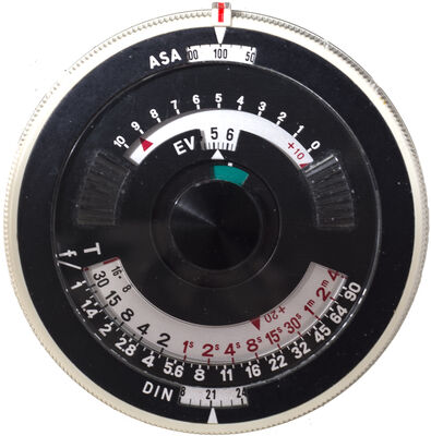
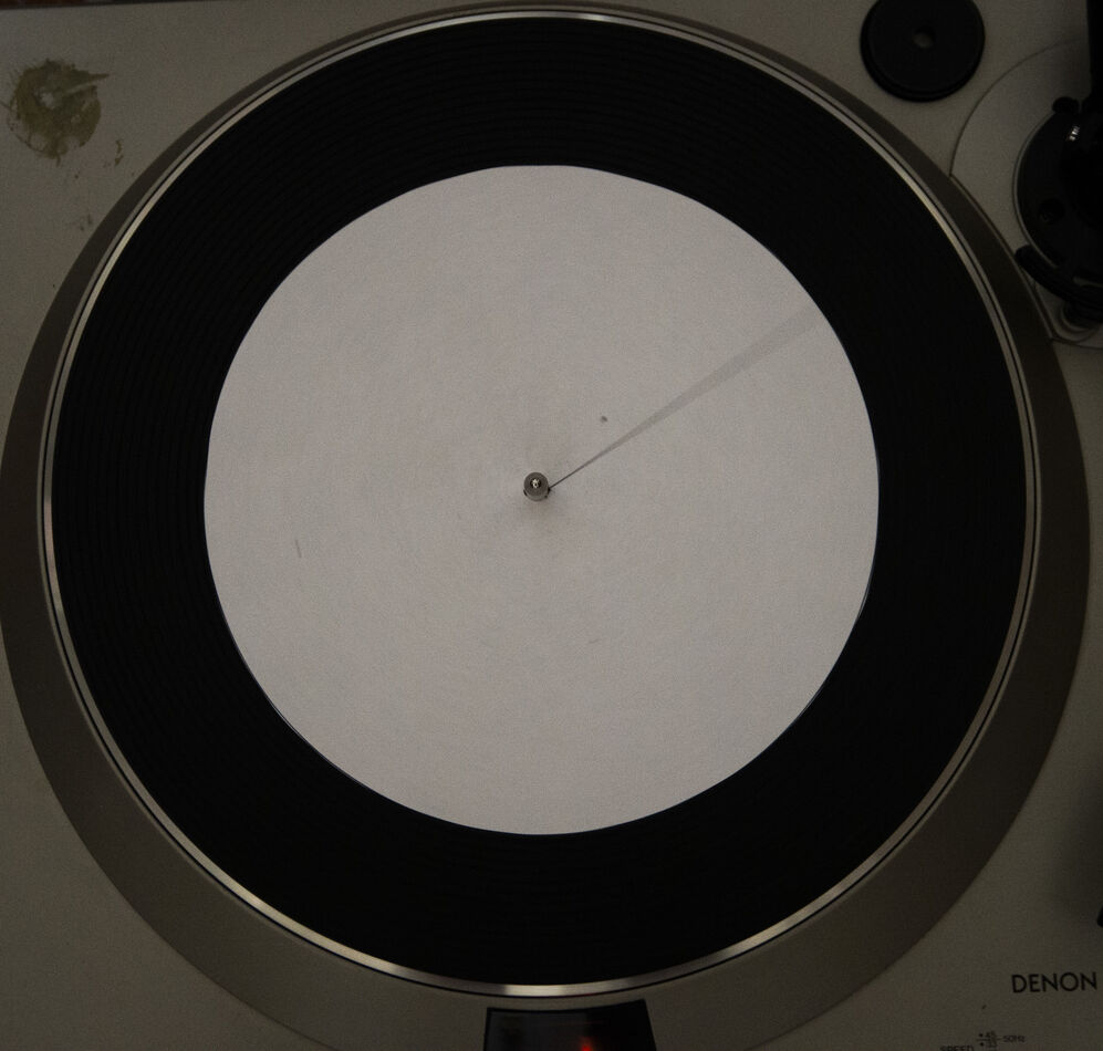
Some guy over the photrio.com suggested to use a turntable to check the shutter speed. I run the turntable at 45rpm and took a shot a 1/60. The angle of the blurred should be 4.2 degrees if the shutter speed is correct. I measured it at 4 degrees. The turntable speed is quite accurate but... it's too slow and even at a relatively slow speed of 1/60 the angle is too small. So I figure is I use a stepper motor which I can make it spin faster and at various speed and accurate speed it would work better.
At speed above flash sync speed I would expect the line to be a curve due to rolling shutter effect.
Feb 17, 2024 05:30:40 #

BebuLamar wrote:
I have a small motor which has a 0.2" diameter shaft. I want to attach a disk about 5-6"in diameter. The disk would in plastic. What is an in expensive way to do this?
If the disk has a hub you can thread it for a set screw, if not you may be able to attach a metal hub with screws through the disk.
But all depends on the use of the motor and disk
Feb 17, 2024 07:11:51 #

Couple of things we need to know.
1. What is the size of the arbor (spindle)?
2. Is it tapered or straight?
Look on a jewelry supply site. They sell threaded tapered buffer spindles that attaches to a motor spindle for the polishing wheels. Very easy to add. The problem you may have depending on how think your disc is, keeping it straight so it does not wobble when you turn it on.
So a google search for buffing arbors and you will find all sorts of solutions.
How rpms will this be spinning at? Do you need a rheostat to control this?
Feb 17, 2024 07:49:36 #
BebuLamar wrote:
Some guy over the photrio.com suggested to use a t... (show quote)
Stepping motor sounds like a good solution to me to produce an accurate speed.
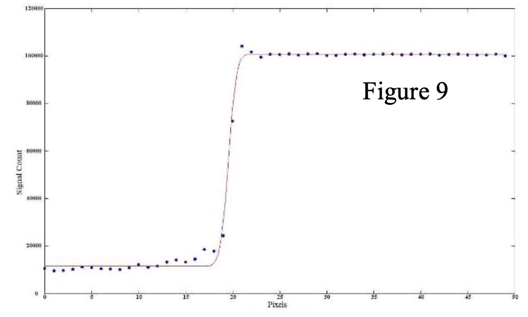
How do you measure the width of a blurry line? I would use a numeric approach similar to what I did when I looked at diffraction (https://static.uglyhedgehog.com/upload/nt/2020/5/9/455146-diffraction_study_20200509.pdf) but that approach requires some programming and the ability to convert an image (or a crop from an image) to a numeric array.
Feb 17, 2024 08:15:17 #
Robertl594 wrote:
Couple of things we need to know. br 1. What is t... (show quote)
The shaft of the motor is 5mm and it's straight no taper Has a flat to accomodate a set screw.
It's a stepping motor so I use a programmable controller with a high speed output module to generate stepping pulses and direction signal. I think I run it up to about 1750rpm.
I will post a picture later.
Feb 17, 2024 08:16:14 #
DirtFarmer wrote:
Stepping motor sounds like a good solution to me to produce an accurate speed.
How do you measure the width of a blurry line? I would use a numeric approach similar to what I did when I looked at diffraction (https://static.uglyhedgehog.com/upload/nt/2020/5/9/455146-diffraction_study_20200509.pdf) but that approach requires some programming and the ability to convert an image (or a crop from an image) to a numeric array.
How do you measure the width of a blurry line? I would use a numeric approach similar to what I did when I looked at diffraction (https://static.uglyhedgehog.com/upload/nt/2020/5/9/455146-diffraction_study_20200509.pdf) but that approach requires some programming and the ability to convert an image (or a crop from an image) to a numeric array.
I import the JPEG into Autocad and use Autocad to measure the angle.
Feb 17, 2024 08:27:40 #
BebuLamar wrote:
The shaft of the motor is 5mm and it's straight no taper Has a flat to accomodate a set screw.
It's a stepping motor so I use a programmable controller with a high speed output module to generate stepping pulses and direction signal. I think I run it up to about 1750rpm.
I will post a picture later.
It's a stepping motor so I use a programmable controller with a high speed output module to generate stepping pulses and direction signal. I think I run it up to about 1750rpm.
I will post a picture later.
Look up Jacob’s Chuck on Amazon. There are loads of them. Could be your answer if you can attach it to the motor spindle. They also make adaptors to do that. Just need to put a pin through the center of your disc and insert into the chuck, then tighten.
Feb 17, 2024 08:29:18 #
Robertl594 wrote:
Look up Jacob’s Chuck on Amazon. There are loads of them. Could be your answer if you can attach it to the motor spindle. They also make adaptors to do that. Just need to put a pin through the center of your disc and insert into the chuck, then tighten.
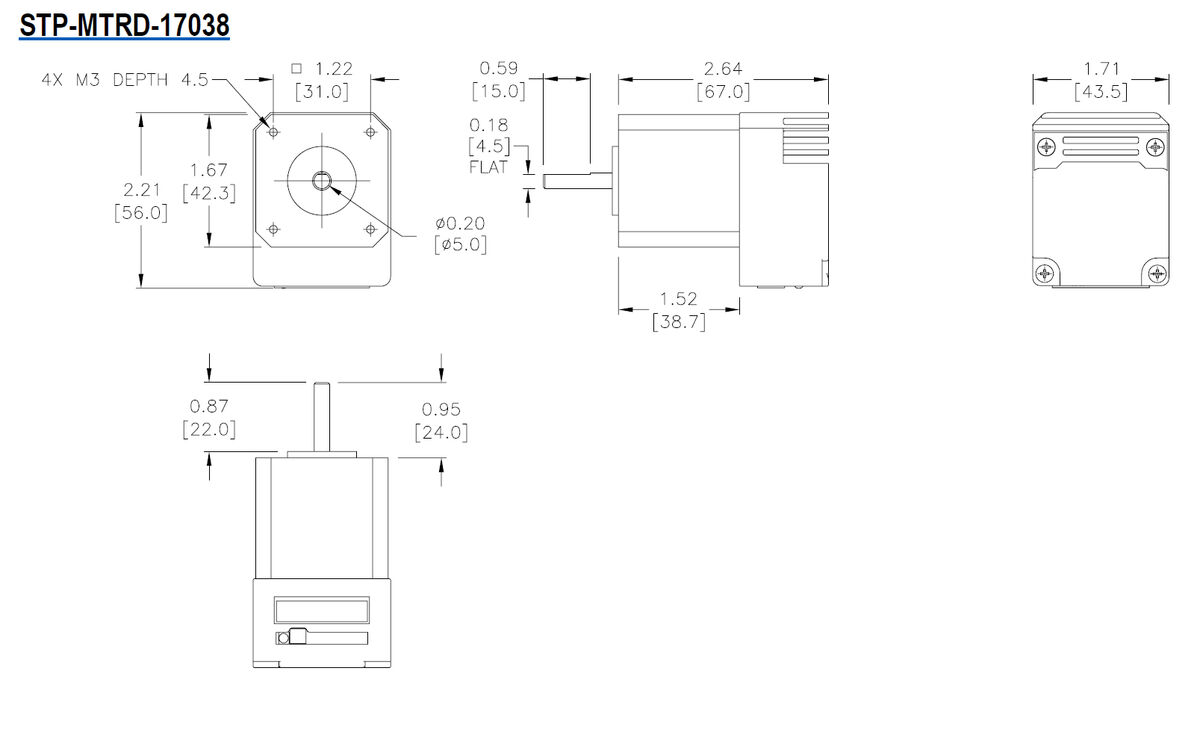
This is the drawing for the motor.
Feb 17, 2024 08:38:42 #
BebuLamar wrote:
This is the drawing for the motor.
Look here. They may make a 5mm. https://images.app.goo.gl/Ckmw5rKFEmUtnjuX9
Feb 17, 2024 08:49:39 #
didn't find an arbor extension for 5mm shaft but I think this would work
https://www.amazon.com/Sydien-Flange-Coupling-Coupler-Connector/dp/B07R9JHCBW/ref=asc_df_B07R9JHCBW/?tag=&linkCode=df0&hvadid=385606297813&hvpos=&hvnetw=g&hvrand=3435544381171077345&hvpone=&hvptwo=&hvqmt=&hvdev=c&hvdvcmdl=&hvlocint=&hvlocphy=9026816&hvtargid=pla-822185381267&mcid=9fe95a171a6f320f8a0e4daf5ac2a807&ref=&adgrpid=77367393823&gclid=Cj0KCQiAz8GuBhCxARIsAOpzk8wMSgcqayZ2sVDkBASIrRwY4uQriRFPgkKhrCrD6uUfN7fPpXEvTcMaAiOAEALw_wcB&th=1
https://www.amazon.com/Sydien-Flange-Coupling-Coupler-Connector/dp/B07R9JHCBW/ref=asc_df_B07R9JHCBW/?tag=&linkCode=df0&hvadid=385606297813&hvpos=&hvnetw=g&hvrand=3435544381171077345&hvpone=&hvptwo=&hvqmt=&hvdev=c&hvdvcmdl=&hvlocint=&hvlocphy=9026816&hvtargid=pla-822185381267&mcid=9fe95a171a6f320f8a0e4daf5ac2a807&ref=&adgrpid=77367393823&gclid=Cj0KCQiAz8GuBhCxARIsAOpzk8wMSgcqayZ2sVDkBASIrRwY4uQriRFPgkKhrCrD6uUfN7fPpXEvTcMaAiOAEALw_wcB&th=1
Feb 17, 2024 09:03:48 #
BebuLamar wrote:
I import the JPEG into Autocad and use Autocad to measure the angle.
Not familiar with Autocad but my impression is that, being a computer aided drawing program, it works with well defined lines. A fuzzy line has an edge that fades from black to white. Just where in the transition do you define the edge? Does Autocad handle that sort of thing? It's going to affect the precision of your measurement.
Feb 17, 2024 09:12:33 #
DirtFarmer wrote:
Not familiar with Autocad but my impression is that, being a computer aided drawing program, it works with well defined lines. A fuzzy line has an edge that fades from black to white. Just where in the transition do you define the edge? Does Autocad handle that sort of thing? It's going to affect the precision of your measurement.
When the JPEG is in Autocad I can draw the 2 lines that matches the lines in the JPEG. A larger angle would be easier to do.
If you want to reply, then register here. Registration is free and your account is created instantly, so you can post right away.